非接触式圆柱直齿轮参数测量方法研究毕业论文
2020-04-15 17:34:48
摘 要
随着生产制造环境日趋复杂,传统的接触式测量方法已经越来越不适用。为了改善齿轮测量的工作环境以及测量精度,提出了一种基于机器视觉的非接触式测量方法。
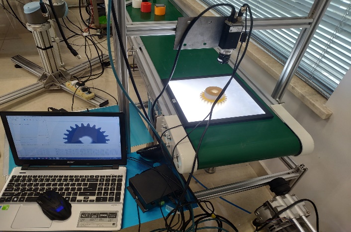
本课题基于机器视觉技术,搭建了一套非接触式的直齿圆柱齿轮的测量平台,通过对被测齿轮的形态特征进行识别并加以比较分析,验证本课题相关的图像处理算法的可行性,具体工作内容如下:
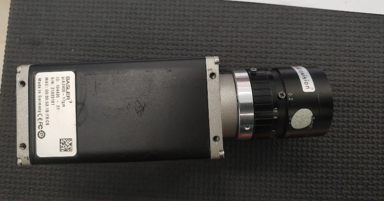
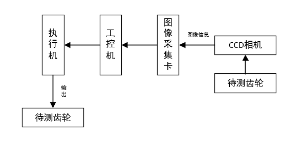
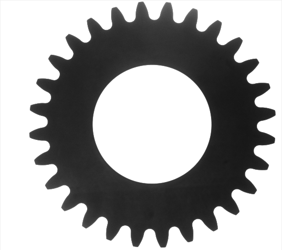
(1)利用CCD相机垂直拍摄被测齿轮,然后将数字化后的图像储存到PC端中。
(2)使用MATLAB软件进行图像处理,比较不同步骤算法的处理效果,选用中值滤波平滑噪声、Canny算子检测边缘、8邻域边缘跟踪算法提取边缘点坐标。
(3)系统标定求出系统像素当量,重心法定位质心、对图像进行掩膜处理、连通域检测得到齿数,并根据齿数和各边缘点到中心的距离计算其它几何参数,分析误差,验证算法的可行性。
关键词:圆柱直齿齿轮 机器视觉 非接触式 图像处理
Research on non-contact measurement method of cylindrical spur gear
Abstract
As the manufacturing environment becomes more complex, traditional contact measurement methods have become increasingly inapplicable. In order to improve the working environment and measurement accuracy of gear measurement, a non-contact measurement method based on machine vision is proposed.
Based on machine vision technology, this project builds a non-contact measuring platform for cylindrical spur gears. By identifying and analyzing the morphological characteristics of the measured gears, the feasibility of the image processing algorithm related to this subject is verified. The specific work content is as follows:
(1) The CCD camera is used to vertically photo the measured gear, and then the digitized image is stored in the PC.
(2) Image processing was performed by using MATLAB software, comparing the processing effects of different step algorithms, and finally decide to use the median filtering smoothing noise and the canny operator edge detection, and 8 neighborhood edge tracking algorithm to extract edge point coordinates.
(3) The system calibration determines the system pixel equivalent. Use the centroid method locates the centroid, mask the image and detect the number of teeth in the connected domain, calculate other geometric parameters according to the number of teeth and the distance from each edge point to the center, analyze the error and verify the feasibility of the algorithm.
Key words: Cylindrical spur gear; Machine vision; Non-contact; Image Processing
目 录
摘 要 I
Abstract II
第1章 绪论 1
1.1 研究的背景、目的和意义 1
1.2 基于机器视觉的圆柱直齿齿轮参数测量的发展及现状 2
1.2.1 国外研究现状 3
1.2.2 国内研究现状 4
1.3 本课题的工作内容与方案 4
第2章 机器视觉测量系统的设计 6
2.1 视觉测量系统的构成 6
2.2视觉测量系统的运行原理概述 8
2.3 成本分析 8
2.4 本章小结 9
第3章 图像处理 10
3.1 图像预处理 10
3.1.1 图像灰度化 10
3.1.2 图像滤波 11
3.1.3 待测齿轮图像滤波处理 13
3.2 图像二值化 16
3.3 区域填充填充孔洞 17
3.4 边缘检测 17
3.4.1 原理简介 18
3.4.2 几种常见的边缘检测算法的比较 18
3.4.3 齿轮图像边缘检测提取 21
3.4.4 结论 22
3.5 本章小结 22
第4章 齿轮参数的测量方案 23
4.1 齿轮中心定位 23
4.2 齿轮参数的测量 24
4.2.1 确定齿数 24
4.2.2 齿顶圆半径齿根圆的测量 28
4.2.3 齿轮模数和分度圆的确定 28
4.3 本章小结 29
第5章 实验结果与误差分析 30
5.1 系统标定 30
5.2 硬件系统引起的误差 31
5.3 图像处理引起的误差 32
5.4 误差补偿 32
5.5 本章小结 32
第6章 总结与展望 33
6.1 总结 33
6.2 展望 33
参考文献 35
致 谢 37
附 录 38
第一章 绪论
1.1 研究的背景、目的和意义
齿轮在机械工业中具有较强的泛用性,目前,我国已经具备完善的齿轮产业体系,齿轮技术体系和齿轮标准技术体系基本形成,在齿轮产量上已经具有了较大突破,但大多数齿轮产品集中在中低端产品,在功率密度、使用寿命上仍存在诸多不足,这些不足之处涉及到齿轮设计、制造、加工、检测等多个方面。
作为机械传动中的主要部件,齿轮的精度直接影响着机械设备的性能和使用寿命,其几何参数测量的精度和实时性等在生产制造中对提高产品生产率有着重大的作用。随着加工制造业的不断发展,产品的生产制造环境日趋复杂,传统的接触式机械测量法耗时长、计算量大、自动化程度低,并且存在测试人员的主观误差,使其越来越不能满足工业化发展的要求,早期的智能化齿轮测量仪器又因为价格因素和使用要求过高等原因不能在行业内普及,机器视觉技术的不断发展改善了这一现状,基于机器视觉的非接触式测量方法具有精度高、速度快、自动化程度高、动态范围大、非接触等优点[1],该测量方法能在很大程度上提高生产效率、保证产品质量、提高生产制造的智能化程度、大大减少人工投入成本,同时还能完成诸多复杂工况下的测量任务,缩短检测时间。例如,在工业生产中,采用基于机器视觉的非接触式齿轮参数测量方法,能有效避免接触式测量产生的表面损伤,并能提高测量效率和减少人为测量误差[2]。
以上是毕业论文大纲或资料介绍,该课题完整毕业论文、开题报告、任务书、程序设计、图纸设计等资料请添加微信获取,微信号:bysjorg。
相关图片展示:
课题毕业论文、开题报告、任务书、外文翻译、程序设计、图纸设计等资料可联系客服协助查找。

