武汉某社区中心暖通空调工程设计毕业论文
2020-04-15 21:41:32
摘 要
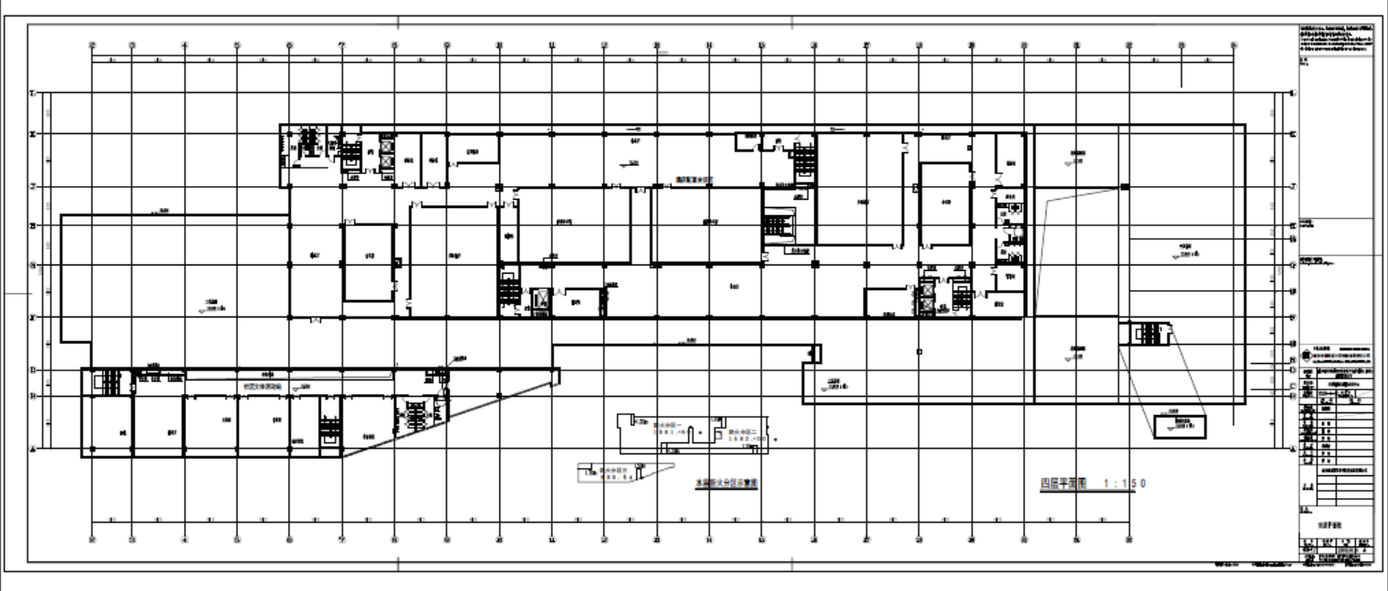
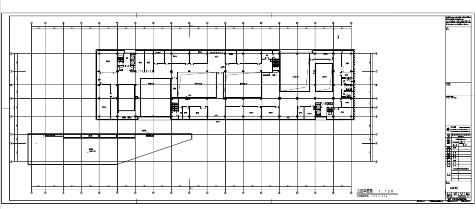
本设计为武汉某社区中心暖通空调工程设计,总建筑面积为44420㎡。地下一层,地上八层,一层~三层为商场,四~五层为酒店配套会议区,六~八层为两栋经济型酒店。地下一层为汽车库、自行车库与设备用房。
本设计负荷计算采用冷负荷系数法计算冷负荷,地上一至三层采用全空气系统,一至三层的派出所和四至八层采用风机盘管加新风系统。在冷负荷计算的基础上完成主机和风机盘管的选型,并通过风量、水量的计算确定风管与水管尺寸,并校核最不利环路的阻力和压头用以确定主机和水泵。空调水系统选择闭式、同程、两管制、变流量、一次泵系统。本工程采用空气源热泵作为冷热源,选用三台海尔牌R22-LSBLGRF630/B螺杆型风冷热泵机组和一台海尔牌R22-LSBLGRF400/C螺杆型风冷热泵机组,机房都设置在三层屋面。四层室内房间单独设置防排烟系统。
关键词:冷负荷 全空气系统 风机盘管 水力计算 冷热源
HVAC Engineering Design of a Community Center in Wuhan
Abstract
The design is the HVAC engineering design for a community center in Wuhan, total construction area of 44420 square meters. The underground is one floor, the ground is eight floors, the first floor to third floor are shopping malls, the fourth to fifth floor are hotel meeting areas, and the sixth to eighth floor are two economic hotels. The underground floor is a garage, bicycle garage and equipment room.
Load calculation cooling load is obtained by using cold load coefficient method in this design.The ground floor to third floor adopt full air system,the police station from the ground to third floor and four to eight layers use fan-coil unit plus fresh air system.The main-machine and fan coils’ choice are based on the calculation of cold-load.And through the numeration of blast volume and water flux,the standard of air duct and water pipe is determined.The most disadvantage resistance and pressure of the loop-road are checked up to ensure the main-machine and water pump.Air conditioning water system is designed as a closed,the same way,two control,variable flow,a pump system.The selection of the project’s cold and heat source is air source heat pump,three Haier brand R22-LSBLGRF630/B and one R22-LSBLGRF400/C air source heat pump screw units are chosen,cold and heat source room is set on the three storey roofing.Smoke control system is provided for interior rooms on the fourth floor separately.
Key Words: cooling load; Full air system; Fan coil; Hydraulic Calculation; Cold and heat source
目 录
摘 要 I
Abstract Ⅱ
第一章 工程概况 1
1.1工程概况 1
1.2动力与能源资料 1
1.3设计要求 1
第二章 空调负荷的计算 3
2.1主要设计参数 3
2.1.1室外气象参数 3
2.1.2室内设计参数 3
2.1.3土建资料 4
2.2空调冷负荷的计算 4
2.2.1外墙、架空楼板或屋面的传热冷负荷 4
2.2.2外窗的温差传热冷负荷 5
2.2.3外窗的太阳辐射冷负荷 5
2.2.4内围护结构的传热冷负荷 6
2.2.5人体显热冷负荷 6
2.2.6灯具冷负荷 7
2.2.7设备显热冷负荷 8
2.2.8人体散湿量与潜热冷负荷 8
2.3空调热负荷的计算 9
2.4空调各房间冷负荷汇总 10
第三章 空调系统方案的确定 12
3.1空调风系统的选取 12
3.2空调水系统的选取 14
第四章 空调风量的计算与设备选型 17
4.1全空气系统设计计算 17
4.1.1夏季送风状态点和送风量 17
4.1.2空调机组的选型 19
4.1.3冬季热负荷的校核 20
4.2风机盘管 新风系统设计计算 20
4.2.1夏季送风状态点和送风量 20
4.2.2风机盘管与新风机组的选型 24
4.2.3冬季热负荷的校核 26
第五章 气流组织计算 27
5.1散流器送风 27
5.1.1一层全空气空调系统 27
5.1.2四层风机盘管连管送风系统 28
5.2侧送风房间 28
第六章 风系统的设计 32
6.1风管材料和形状的确定 32
6.2送、回风管的布置 32
6.3风管设计 32
6.3.1风管水力计算步骤 32
6.3.2送风管水力计算 33
6.3.3回风管水力计算 38
6.3.4新风管水力计算 41
6.4新风系统风管水力计算 41
6.4.1一层新风系统风管水力计算 41
6.4.2四层新风系统风管水力计算 42
6.4.3五层新风系统风管水力计算 43
第七章 空调冷热源的确定 45
7.1空调冷热源的种类及其特点 45
7.2冷热源的选型 46
第八章 水系统的设计 48
8.1冷冻水管路设计计算步骤 48
8.2冷冻水供回水水力计算 49
8.2.1分区一冷冻水供回水水力计算 49
8.3水泵的计算与选型 54
8.3.1冷冻水泵设计规范 54
8.3.2冷冻水泵的选型 55
8.4冷凝水排放系统设计 56
8.5循环水系统的补水与定压 57
8.5.1水系统的补水 57
8.5.2补水泵的选择与设置 58
8.5.3水系统的定压 59
8.5.4膨胀水箱的设计与计算 59
8.6分水器和集水器的选择 61
8.7水过滤器的选择 62
第九章 通风与防排烟设计 63
9.1防烟系统设计 63
9.1.1设计规定与系统选择 63
9.2排烟系统设计 63
9.2.1防烟分区与系统选择 63
9.2.2机械排烟量的计算与排烟风机的选择 64
第十章 空调系统的消声与减振 66
10.1空调系统的消声设计 66
10.2空调系统的减振设计 66
第十一章 管道的保温与防腐 67
11.1保温设计 67
11.2防腐设计 67
参考文献 68
附表一 冷负荷汇总表 69
附表二 一层其余房间散流器气流组织计算 73
附表三 四层其余房间散流器气流组织计算 74
附表四 侧送风气流组织计算 76
附表五 一层金融服务设施送风管水力计算表 78
附表六 一层其余房间送风管水力计算表 81
附表七 一层其余房间回风管水力计算表 83
附表八 一层新风管水力计算表 86
以上是毕业论文大纲或资料介绍,该课题完整毕业论文、开题报告、任务书、程序设计、图纸设计等资料请添加微信获取,微信号:bysjorg。
相关图片展示:

课题毕业论文、开题报告、任务书、外文翻译、程序设计、图纸设计等资料可联系客服协助查找。


