厦门第二东通道中航道预应力混凝土连续梁桥设计(90 m 150 m 150 m 90 m)毕业论文
2020-04-21 16:59:45
摘 要
本设计是根据设计任务书的要求和《公路桥规》的规定,优化设计厦门第二东通道中航道
预应力混凝土连续梁方案。首先根据工程概况和规范要求进行该桥的方案设计和比选,选定的方案为变跨度四跨预应力混凝土连续梁桥,采用分离式单箱双室变高度箱型截面,腹板形式为斜腹板,施工方式为满堂支架现浇施工。根据公路桥规和设计手册初步拟定桥跨布置和截面尺寸后,利用Midas 软件建立桥梁模型并计算结构的恒载、活载及次内力等荷载,接着进行荷载组合并画出包络图;然后手算预应力钢筋的估算与布置、截面几何特性、预应力损失等;然后通过手算对上部结构进行验算,结果均满足设计要求。最后进行下部结构初步设计,采用球型钢支座、双柱墩和桩基础。此外,本设计也进行了工程量预算、施工图绘制等工作。
关键词:方案设计 连续梁桥 预应力 满堂支架施工
Design of Prestressed Concrete Continuous Girder Bridge in Middle Channel of Xiamen Second East Passage
Abstract
According to the requirements of the design document and the regulations of Highway Bridge Regulation, this design compares and designs the middle channel of the second East passage in Xiamen . Firstly, according to the general situation of the project and the requirements of the code, the scheme of the bridge is designed and compared. The selected scheme is a variable-span four-span prestressed concrete continuous girder bridge, with separate single box and double chambers,variable height box section, and inclined web plate. The construction method is full bracket cast-in-place construction . After drawing up the layout and section size of the bridge span according to the highway bridge gauge and design manual, the bridge model is established by using Midas software, and the dead load, live load and an internal force of the structure are calculated, and then the load combination is carried out and the envelope diagram is drawn. Then calculate the calculation and arrangement of the prestressed steel bar, the geometric characteristic of section, and the loss of prestressing force. Then the superstructure is checked by hand calculate, and the results meet the design requirements. Finally, the preliminary design of the substructure is carried out, using the ball steel support, the double column pier and the pile foundation.In addition, this design also carries on the project quantity budget, the construction drawing and so on work.
Key Words: Design; Continuous girder bridge; Prestress;Full bracket cast-in-place construction
第一章 方案设计 1
1.1 跨径布置 1
1.2 顺桥向设计 2
1.3 横桥向设计 3
第二章 恒载计算 7
2.1 节段划分及截面几何要素计算 7
2.2 一期恒载计算 8
2.3 二期恒载计算 9
2.4 总恒载效应 11
第三章 活载计算 15
3.1 汽车荷载 15
3.1 最大、最小弯矩计算 16
3.2 最大、最小剪力计算 17
第四章 次内力计算 18
4.1 温度次内力计算 18
4.2 支座沉降次内力计算 23
第五章 内力组合及内力包络图 25
5.1 频遇组合 25
5.2 准永久组合 26
5.3 基本组合 27
第六章 预应力筋的计算与布置 29
6.1 原理与方法 29
6.2预应力筋的配置 29
6.3钢束布置 29
第七章 净截面及换算截面几何特性计算 46
7.1 概述 46
7.2 净截面几何性质计算 46
7.3 换算截面性质计算 50
第八章 预应力损失及有效预应力计算 52
8.1 控制应力及有关参数计算 52
8.2 摩擦损失σl1 53
8.3 锚具回缩损失σl2 59
8.4 弹性压缩损失σl4 65
8.5 应力松弛损失σl5 66
8.6 收缩徐变损失σl6 66
8.7 预应力损失组合及有效预应力计算 68
第九章 承载能力极限状态验算 71
9.1 正截面承载力验算 71
9.2 斜截面抗剪承载力验算 73
第十章 正常使用极限状态验算 75
10.1 抗裂验算 75
第十一章 持久状况和短暂状况应力验算 78
11.1 持久状况截面混凝土法向应力验算 78
10.2 短暂状态应力验算 78
第十二章 墩及桩基础设计与计算 82
12.1 支座 82
12.2 墩身设计与验算 83
12.3承台设计 86
12.4 桩基础设计 86
第十三章 桥梁工程预算 88
13.1 工程量估算 88
13.2 工程造价预算 88
参考文献 92
第一章 方案设计
1.1 跨径布置
1.1.1 标准跨径
厦门第二东通道中航道起点桩号:K1+512,实际桥长480m,本联设计采用变截面连续箱梁结构形式。为了在整体上保证桥的整体协调及美观性,跨径布置时,要和前后联协调好,通过计算调整,最终确定本联的跨径布置如下:
90m 2×150m 90m=480m
标准跨径(相邻墩身轴线距离)布置图示如图 1-1。


0.47m 89.5m 2×150m 89.5m 0.47m

相关图片展示:
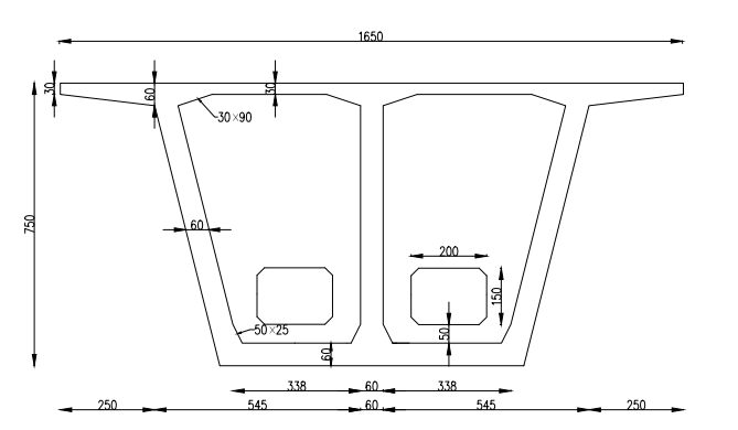
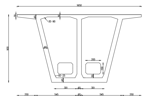
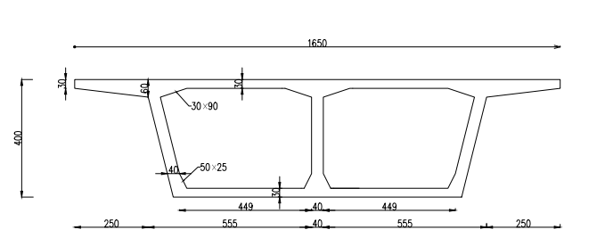
课题毕业论文、开题报告、任务书、外文翻译、程序设计、图纸设计等资料可联系客服协助查找。


